PCB Cupid: Lighting Up 8x8 LED Matrix Arrays with ESP32 and MD_MAX72XX
After many years spent in the trenches of embedded systems—witnessing the evolution from clunky microcontrollers to sleek, Wi-Fi-enabled boards—I still find a childlike thrill in the glow of an LED matrix. There’s something magical about transforming raw binary into a living, breathing display. Today, I want to take you on a journey through my latest project: bringing the words “PCB Cupid” to life on an 8x8 LED matrix array using an ESP32 and the MD_MAX72XX library.
Why LED Matrices Still Matter
In an age of high-res OLEDs and touchscreens, you might ask: why bother with an 8x8 LED matrix? Here’s why they remain close to my heart:
· Simplicity Meets Power: Minimalist hardware, maximal creative potential.
· Instant Feedback: See your code come alive, pixel by pixel.
· Perfect for Learning: Bitwise operations, timing, hardware interfaces—all in one compact package.

The Hardware: Old School Meets New School
| Component | Details |
|---|---|
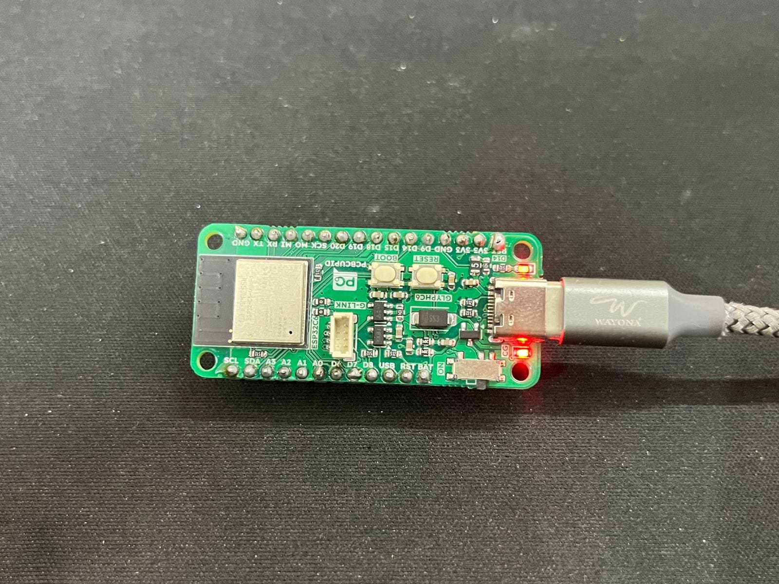
| Microcontroller | ESP32 (Glyph C6, ESP32-C6 based board) |
| Display Module | 8-in-1 8x8 Dot Matrix with MAX7219 |
| Power Source | USB or 3.3V Regulated Supply |
| Connectivity | SPI (MOSI, SCLK, CS) |
| Extras | Breadboard, jumper wires, laptop |
Pro Tip: Always check your power supply. Even after years, I’ve seen more projects fail from brownouts than bad code!
Wiring: The Art of Connection
| ESP32 GPIO | Matrix Module Pin |
|---|---|
| GPIO18 | CS (Chip Select) |
| GPIO23 | MOSI (DIN) |
| GPIO19 | CLK |
| GND | GND |
| 3.3V | VCC |
Note: Stable power is key. Many MAX7219 modules tolerate 3.3V logic, but a solid 5V supply keeps things bright and reliable.
The Code: Pixels, Bitmaps, and a Dash of Wisdom
1. Library Setup
Install these libraries in Arduino IDE:
· MD_MAX72XX (by MajicDesigns)
· SPI.h (built-in)
2. Custom Letter Bitmaps
After years of working with displays, I’ve learned: default fonts rarely do justice to your message. For “PCB Cupid,” I crafted each letter as an 8x8 bitmap—a satisfying exercise in digital calligraphy.
const uint8_t letters[8][8] = {
  // P, C, B, C, U, P, I, D
  {0x7F, 0x11, 0x11, 0x11, 0x0E, 0x00, 0x00, 0x00},
  {0x3E, 0x41, 0x41, 0x41, 0x22, 0x00, 0x00, 0x00},
  {0x7F, 0x49, 0x49, 0x49, 0x36, 0x00, 0x00, 0x00},
  {0x3E, 0x41, 0x41, 0x41, 0x22, 0x00, 0x00, 0x00},
  {0x3E, 0x40, 0x40, 0x40, 0x3E, 0x00, 0x00, 0x00},
  {0x7F, 0x11, 0x11, 0x11, 0x0E, 0x00, 0x00, 0x00},
  {0x41, 0x7F, 0x41, 0x00, 0x00, 0x00, 0x00, 0x00},
  {0x7F, 0x41, 0x41, 0x22, 0x1C, 0x00, 0x00, 0x00}
};
3. Orientation: When Hardware Has a Mind of Its Own
Despite all my experience, hardware still surprises me. The matrix was mounted 90° off—turning “PCB Cupid” into a cryptic puzzle. The fix? Rotate each bitmap 90° anti-clockwise in code. Here’s a snippet from my setup routine:
void setup() {
  mx.begin();
  mx.control(MD_MAX72XX::INTENSITY, 1);

  for (int panel = 0; panel < 8; panel++) {
    int letter_index = 7 - panel;
    for (int row = 0; row < 8; row++) {
      uint8_t rowData = 0;
      for (int col = 0; col < 8; col++) {
        if (letters[letter_index][col] & (1 << row)) {
          rowData |= (1 << (7 - col));
        }
      }
      mx.setRow(panel, row, rowData);
    }
  }
}
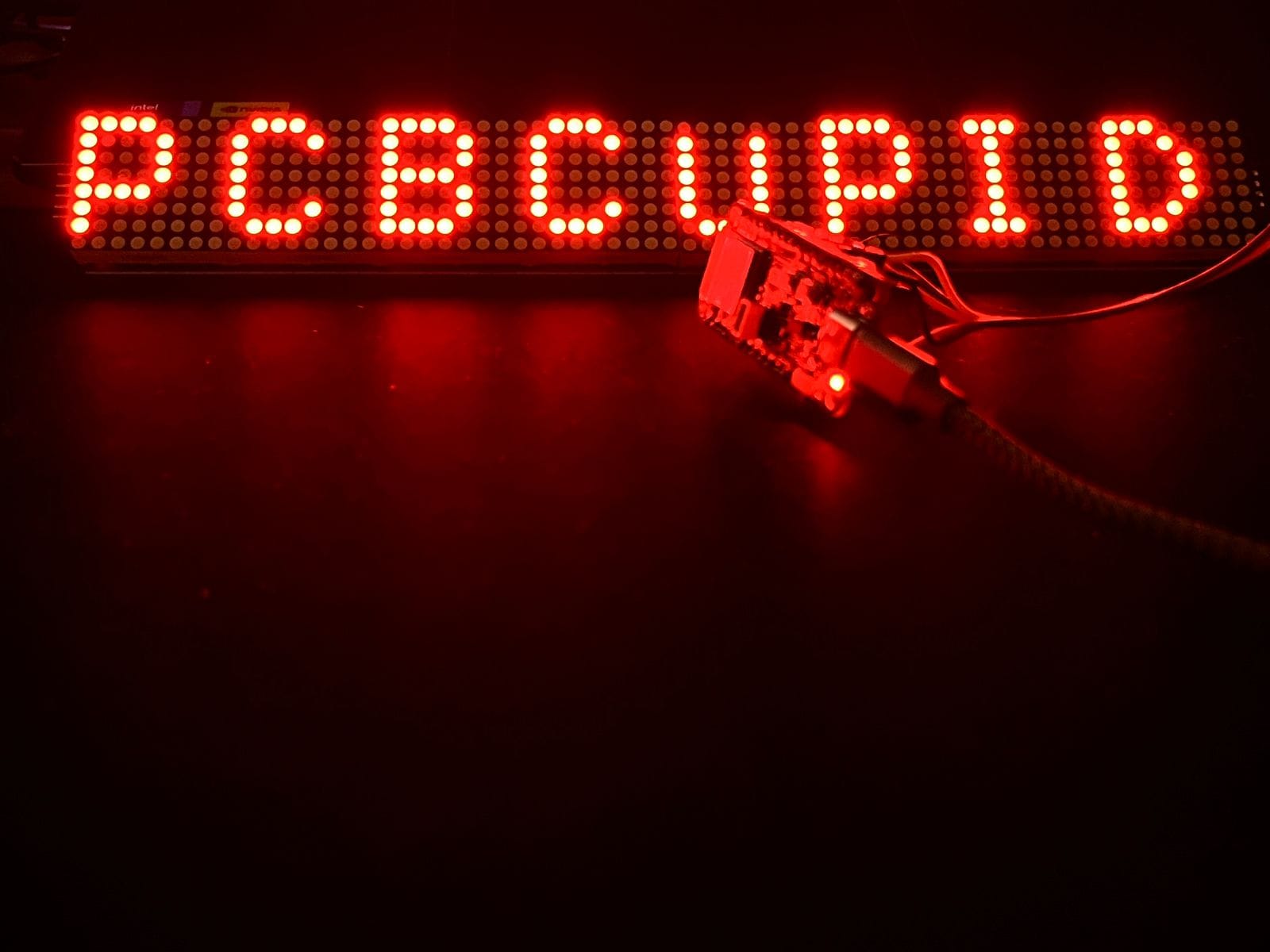
The Result: “PCB Cupid” in Glorious 8x8
The first time the matrix lit up, spelling out “PCB CUPID” from left to right, I felt that familiar spark. Each letter, crisp and clear, danced across its own panel—a simple message, but a testament to the joy of hands-on engineering.
Lessons from a Lifetime (and a Few Debugging Sessions)
· Orientation Matters: Always check your physical setup before blaming your code.
· Pixel Art is an Art: Designing legible letters on 8x8 grids is a delightful challenge.
· Power is Everything: Don’t let a weak supply dim your creativity.
· Libraries are Tools, Not Crutches: Dive into the code, understand what’s under the hood.
What’s Next? The Future is Bright (and Blinking)
With the basics nailed down, the possibilities are endless:
· Scrolling text and animations (imagine a blinking heart for “Cupid”)
· Bluetooth or Wi-Fi for real-time message updates
· Custom PCBs for a sleek, integrated look
Final Thoughts
After three years, projects like this remind me why I fell in love with embedded systems. It’s not just about blinking lights—it’s about turning ideas into reality, one pixel at a time. Whether you’re a seasoned engineer or just starting out, never underestimate the magic of a simple LED matrix. Keep building, keep learning, and let your creativity shine—literally!
Author: Yashwanth Chityala
Linked In: https://www.linkedin.com/in/yashwanth-chityala/