Interfacing PCBCupid's Glyph C6 Board with Adafruit's BNO055 IMU Sensor: A Comprehensive Guide to Motion Sensing and Orientation Tracking
The world of Internet of Things (IoT) applications increasingly demands precise motion sensing and orientation tracking capabilities. From autonomous drones navigating complex environments to wearable devices monitoring human movement, the ability to accurately determine spatial orientation has become fundamental to modern embedded systems. This comprehensive guide explores the powerful combination of PCBCupid's Glyph C6 development board with Adafruit's BNO055 Intelligent Motion Unit (IMU) sensor, demonstrating how this pairing delivers professional-grade motion sensing capabilities at an accessible price point.

The PCBCupid Glyph C6 represents a significant advancement in compact development boards, featuring the latest ESP32-C6 RISC-V processor with integrated Wi-Fi 6, Bluetooth 5.3, and Zigbee 3.0 connectivity[1]. When paired with the Adafruit BNO055, which incorporates sophisticated sensor fusion algorithms running on an onboard ARM Cortex-M0+ microcontroller[2], developers gain access to drift-free orientation data without the complexity typically associated with multi-sensor integration. This combination eliminates the traditional challenges of implementing sensor fusion algorithms, allowing developers to focus on application-specific innovation rather than low-level sensor mathematics

The BNO055's intelligent design processes data from its integrated 3-axis accelerometer, gyroscope, and magnetometer, delivering ready-to-use orientation information in multiple formats including Euler angles, quaternions, and linear acceleration vectors[3]. This approach significantly reduces development time and computational overhead on the host processor, making it ideal for battery-powered IoT applications where efficiency is paramount.
Hardware Overview
PCBCupid Glyph C6: Compact Powerhouse for IoT Applications
The Glyph C6 development board showcases modern embedded system design in a remarkably compact 50.8mm x 22.8mm x 1.6mm form factor[1]. At its heart lies the ESP32-C6, a 32-bit RISC-V single-core processor operating at 160 MHz, representing Espressif's latest generation of IoT processors with enhanced performance and energy efficiency[4]. This processor architecture provides significant advantages over traditional ARM-based alternatives, offering improved power consumption characteristics crucial for battery-operated applications.
The board's connectivity capabilities position it at the forefront of IoT development. Wi-Fi 6 support ensures future-proof wireless communication with improved efficiency and reduced latency compared to previous Wi-Fi standards[5]. Bluetooth 5.3 integration enables low-energy communication with mobile devices and other peripherals, while Zigbee 3.0 support opens possibilities for mesh networking applications in smart home and industrial automation scenarios[4]. The coexistence of these wireless protocols on a single chip, sharing the same antenna, demonstrates sophisticated RF engineering that maximizes functionality while minimizing board complexity.
Memory specifications include 512KB SRAM and 4MB Flash storage, providing adequate space for complex applications while maintaining cost-effectiveness[1]. The board features 21 GPIO pins with comprehensive peripheral support including 12-bit ADCs, I2C, SPI, UART, and USB Serial interfaces[5]. This extensive I/O capability ensures compatibility with a wide range of sensors and actuators, making the Glyph C6 suitable for diverse application scenarios.
Power management represents another strength of the Glyph C6 design. The integrated USB-C connector provides convenient programming and power delivery, while the built-in LiPo/Li-ion battery charger with monitoring circuit enables portable applications[1]. Automatic switching between USB and battery power, combined with the ability to measure battery capacity and control power states via an onboard slide switch, demonstrates thoughtful consideration for real-world deployment scenarios. The GLINK connector's compatibility with QWIIC and STEMMA QT ecosystems facilitates rapid prototyping by enabling tool-free sensor connections[4].

Adafruit BNO055 IMU: Intelligent Sensor Fusion in a Single Package
The Adafruit BNO055 represents a paradigm shift in IMU sensor design, integrating not just multiple sensors but also the computational intelligence required to process their data meaningfully[2]. This System-in-Package (SiP) solution combines a 14-bit triaxial accelerometer, 16-bit triaxial gyroscope with a ±2000 degrees per second range, a triaxial geomagnetic sensor, and a 32-bit ARM Cortex-M0+ microcontroller running Bosch's proprietary BSX3.0 FusionLib software[6].

The accelerometer component measures linear acceleration across three axes with programmable ranges from ±2g to ±16g, enabling applications from gentle tilt detection to high-impact monitoring[6]. It's 14-bit resolution provides sufficient precision for most motion sensing applications while maintaining reasonable power consumption. The integrated gyroscope offers angular velocity measurement with exceptional sensitivity, crucial for detecting rapid orientation changes that might be missed by accelerometer-only solutions.
The magnetometer functionality extends beyond simple compass applications, providing absolute heading reference that helps correct gyroscope drift over extended periods[7]. This three-sensor combination, when processed through the onboard fusion algorithms, delivers orientation accuracy that would require significant computational resources and complex algorithms if implemented on the host processor. The sensor outputs data at rates up to 100Hz for orientation and acceleration measurements, with magnetometer data available at 20Hz[3].
Communication with the host processor occurs via I2C interface, utilizing the industry-standard protocol that minimizes wiring complexity while maintaining reliable data transfer[8]. The sensor supports both 3.3V and 5V logic levels, ensuring compatibility with diverse microcontroller platforms[9]. STEMMA QT connectors on the Adafruit breakout board enable chainable connections, allowing multiple sensors to share the same I2C bus without soldering requirements.
The BNO055's intelligent processing capabilities extend to automatic calibration routines that continuously adapt to environmental conditions[2]. This self-calibration feature significantly reduces the setup complexity typically associated with multi-axis sensor systems, making the device accessible to developers without extensive sensor fusion expertise.
Connection and Setup
Physical Connections and I2C Configuration
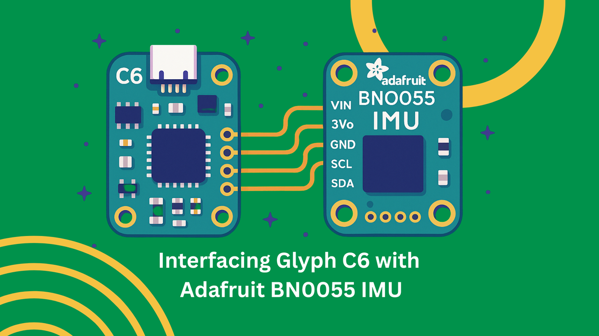
Interfacing the Glyph C6 with the BNO055 leverages the I2C communication protocol, which requires only four connections: power (VCC), ground (GND), serial data (SDA), and serial clock (SCL)[10]. The ESP32-C6 designates GPIO 21 and GPIO 22 as the default I2C pins for SDA and SCL respectively, following established ESP32 conventions[11]. However, the flexibility of the ESP32's GPIO matrix allows alternative pin assignments if required by specific application constraints.
For reliable operation, ensure the BNO055 receives stable 3.3V power supply, which the Glyph C6 can provide through its onboard regulator[1]. The sensor's built-in voltage regulation accepts input voltages from 3.3V to 5V, but 3.3V operation is recommended for compatibility with the ESP32-C6's logic levels[9]. Ground connections must be solid to prevent noise injection that could affect sensor readings, particularly important given the BNO055's high sensitivity to environmental factors.
The I2C bus requires pull-up resistors on both SDA and SCL lines, which the BNO055 breakout board provides as 10kΩ resistors[9]. These resistors ensure proper logic level transitions and signal integrity across the bus. When connecting multiple I2C devices, verify that the total bus capacitance remains within I2C specifications to maintain communication reliability.
The BNO055's default I2C address is 0x28, but this can be changed to 0x29 by connecting the ADR pin to 3.3V, enabling two BNO055 sensors on the same bus[9]. Address selection must be performed before power-up to ensure proper device enumeration during system initialization.
Arduino IDE Setup and Library Installation
Development with the Glyph C6 and BNO055 combination requires proper Arduino IDE configuration for ESP32-C6 support. Install the ESP32 board package through the Arduino IDE Board Manager, ensuring you select the latest version that includes ESP32-C6 support[12]. The ESP32-C6 represents newer technology compared to traditional ESP32 variants, so recent board package versions are essential for proper functionality.
Library installation involves two primary components: the Adafruit BNO055 library and the Adafruit Unified Sensor library, which provides standardized interfaces for sensor data access[13]. These libraries abstract the low-level I2C communication details and provide convenient functions for sensor configuration and data retrieval. Installation through the Arduino Library Manager ensures version compatibility and automatic dependency resolution.
For ESP32-C6 specific configurations, the I2C initialization may require explicit pin assignment using Wire.begin(SDA_PIN, SCL_PIN) format rather than relying on default pin assignments[14]. This explicit configuration prevents communication issues that can arise from hardware abstraction layer differences between ESP32 variants.
Basic sensor initialization involves creating a BNO055 object, calling the begin() function to establish I2C communication, and setting the desired operation mode. Error handling during initialization is crucial, as I2C communication problems can result from incorrect wiring, power supply issues, or address conflicts[15].
BNO055 Operation Modes and NDOF Selection
Understanding Available Operation Modes
The BNO055 offers multiple operation modes designed for different application requirements, ranging from simple sensor data output to complex sensor fusion[16]. These modes can be broadly categorized into non-fusion modes, which provide raw sensor data, and fusion modes, which combine multiple sensor inputs to produce orientation information. Understanding the distinctions between these modes is crucial for selecting the optimal configuration for specific applications.
Non-fusion modes include accelerometer-only, gyroscope-only, and magnetometer-only configurations, useful for applications requiring single-sensor data or custom fusion implementations[17]. These modes provide direct access to individual sensor outputs without onboard processing, offering maximum flexibility at the cost of increased host processor requirements for meaningful orientation calculation.
Fusion modes leverage the BNO055's onboard ARM Cortex-M0+ processor to combine sensor data intelligently[18]. The most significant fusion modes include IMU mode (accelerometer and gyroscope only), COMPASS mode (accelerometer and magnetometer), M4G mode (accelerometer, magnetometer with gyroscope bias estimation), and the comprehensive NDOF modes that utilize all three sensor types.
NDOF Mode: Optimal Choice for Dynamic Systems
Nine Degrees of Freedom (NDOF) mode represents the BNO055's most sophisticated operation mode, utilizing data from all three sensor types—accelerometer, gyroscope, and magnetometer—to provide absolute orientation with minimal drift[16]. This mode implements advanced sensor fusion algorithms that compensate for individual sensor limitations, delivering orientation accuracy superior to any single sensor approach.
NDOF mode excels in dynamic applications where the sensor experiences rapid orientation changes, complex motion patterns, or extended operation periods[19]. The fusion algorithm continuously adapts to sensor characteristics and environmental conditions, providing stable orientation output even when individual sensors experience temporary disturbances or calibration drift.
The mode offers two variants: standard NDOF and NDOF_FMC_OFF[20]. Standard NDOF includes Fast Magnetic Calibration (FMC), which accelerates magnetometer calibration by using gyroscope data to validate magnetic field measurements[7]. This feature enables rapid calibration, often requiring only partial figure-8 motions rather than complete calibration routines. NDOF_FMC_OFF disables this feature, relying solely on magnetometer data for magnetic calibration, which may require more extensive calibration procedures but can provide more consistent results in environments with stable magnetic fields.
The choice between NDOF variants depends on application requirements and environmental conditions. Standard NDOF with FMC enabled is generally preferred for dynamic applications where quick setup is important, while NDOF_FMC_OFF may be better suited for precision applications in magnetically stable environments[7].
NDOF mode outputs orientation data at 100Hz, providing sufficient temporal resolution for most motion tracking applications[3]. The high output rate, combined with the sophisticated fusion algorithms, makes the NDOF mode particularly suitable for applications such as drone stabilization, robotics navigation, and virtual reality motion tracking, where orientation accuracy and responsiveness are critical.
MEMS IMU Limitations and Challenges
Sensor Drift and Bias Instability
Microelectromechanical Systems (MEMS) based IMUs face fundamental limitations arising from their microscale manufacturing processes and physical operating principles[21]. Sensor drift represents the most significant challenge, manifesting as gradual deviation from true measurements over time due to accumulated integration errors and internal bias instabilities[22]. This drift occurs because gyroscopes measure angular velocity, requiring integration to determine orientation, and any constant bias error becomes magnified through this integration process.
Bias instability in gyroscopes stems from multiple sources including thermal fluctuations, mechanical stress, and electronic noise within the MEMS structure[23]. The gyroscope drift is primarily composed of two components: bias instability, a slowly changing near-DC variable, and angular random walk (ARW), representing higher frequency noise that accumulates through integration[22]. These parameters are typically specified in degrees per hour, with consumer-grade MEMS gyroscopes often exhibiting drift rates of several degrees per hour compared to tactical-grade units that may achieve drift rates below 1 degree per hour.
Accelerometers also experience bias drift, though the effects are somewhat less pronounced in orientation applications since gravity provides a constant reference vector[24]. However, accelerometer bias becomes critical in applications requiring linear acceleration measurement or dead-reckoning navigation, where position must be calculated through double integration of acceleration data.
The integration process inherent in converting angular velocity to orientation amplifies low-frequency errors while attenuating high-frequency noise[23]. This frequency response characteristic means that even small constant biases in gyroscope readings result in continuously growing orientation errors. For applications requiring long-term accuracy, some form of external reference or periodic correction becomes necessary to prevent unbounded error accumulation.
Environmental Sensitivity and External Factors
MEMS IMU sensors exhibit significant sensitivity to environmental factors that can substantially impact measurement accuracy[25]. Temperature variations affect sensor characteristics through thermal expansion of mechanical elements, changes in electronic component values, and thermal stress within the MEMS structure[26]. Consumer-grade MEMS sensors typically show temperature coefficients that can introduce errors of several percent per degree Celsius change.
Vibration and mechanical shock represent another category of environmental sensitivity, particularly affecting accelerometer readings[25]. High-frequency vibrations can alias into the measurement bandwidth, creating apparent accelerations that don't correspond to actual device motion. This aliasing effect becomes problematic in applications such as vehicle-mounted systems or industrial environments with significant machinery vibration.
Magnetic interference poses unique challenges for magnetometer-based heading determination[25]. Local magnetic fields from ferromagnetic materials, electrical currents, or electronic devices can overwhelm the Earth's magnetic field, leading to significant heading errors. Urban environments, vehicles, and indoor spaces often contain magnetic disturbances that can cause heading errors of tens of degrees. The BNO055's intelligent calibration algorithms attempt to compensate for these effects, but severe magnetic disturbances can overwhelm any calibration routine.
The proximity of other electronic components can also introduce electromagnetic interference that affects sensor readings. High-current switching circuits, radio frequency transmitters, and digital clock signals can couple into sensitive analog sensor circuits, introducing noise or systematic errors that degrade measurement quality.
Integration Errors and Long-term Accuracy Limitations
The mathematical integration required to convert sensor measurements into orientation and position information introduces cumulative errors that grow over time[24]. These integration errors arise from several sources: discretization errors due to finite sampling rates, numerical precision limitations in computational hardware, and the fundamental challenge of reconstructing continuous motion from discrete sensor measurements.
Sampling rate limitations create aliasing effects when actual motion contains frequency components above the Nyquist frequency[21]. Consumer MEMS IMUs typically operate at sampling rates between 100Hz and 1000Hz, which may be insufficient for capturing rapid motion transients or high-frequency vibrations. These unsampled motion components can appear as lower-frequency signals that corrupt the integration process.
Quantization noise from analog-to-digital converters adds random errors to each sensor measurement[26]. While individual quantization errors may be small, their accumulation through integration can result in significant long-term drift. The random walk nature of accumulated quantization noise means that position errors grow proportionally to the square root of time, even in the absence of other error sources.
The fundamental challenge of MEMS IMU accuracy lies in the cost-performance trade-off inherent in mass-production sensors[27]. High-precision navigation-grade IMUs can cost thousands of dollars and require sophisticated calibration procedures, while consumer MEMS units achieve reasonable accuracy at dramatically lower costs but with corresponding limitations in long-term stability and environmental robustness.
Orientation Representations: Euler Angles vs. Quaternions
Euler Angles: Intuitive but Problematic
Euler angles provide the most intuitive representation of 3D orientation, describing rotation as three sequential rotations about coordinate axes[28]. The standard aerospace convention defines these rotations as roll (rotation about the longitudinal axis), pitch (rotation about the lateral axis), and yaw (rotation about the vertical axis)[29]. This representation aligns closely with human spatial intuition, making Euler angles the preferred choice for user interfaces and applications where human operators need to understand orientation data directly.
The mathematical simplicity of Euler angles makes them attractive for basic applications[30]. Each angle directly corresponds to a physical rotation that can be visualized and understood without complex mathematical training. For applications involving small orientation changes or those confined to limited angular ranges, Euler angles provide adequate representation with minimal computational overhead.
However, Euler angles suffer from a fundamental mathematical limitation known as gimbal lock[31]. This phenomenon occurs when two of the three rotation axes become aligned, effectively reducing the system's degrees of freedom from three to two[32]. Gimbal lock creates singularities in the mathematical representation where small orientation changes require large changes in angle values, leading to discontinuous and unpredictable behavior in control systems or animation applications.
The gimbal lock problem is not merely theoretical but has practical implications for any system using Euler angles for orientation control[33]. When the middle axis in the rotation sequence approaches ±90 degrees, the first and third axes become aligned, creating ambiguous representations where multiple angle combinations produce identical orientations[31]. This ambiguity can cause erratic behavior in control systems and make smooth interpolation between orientations impossible in certain configurations.
Quaternions: Mathematical Elegance and Practical Advantages
Quaternions represent 3D rotations using four components (w, x, y, z) forming a hypercomplex number system that elegantly avoids the singularities inherent in Euler angle representations[34]. The quaternion representation encodes rotation as a single rotation about an arbitrary axis, which can represent any possible 3D orientation without mathematical singularities[29]. This property makes quaternions particularly valuable for applications requiring smooth orientation interpolation or control system implementation.
The mathematical properties of quaternions provide significant computational advantages[35]. Quaternion multiplication directly corresponds to rotation composition, making it straightforward to combine multiple rotations or apply rotations to vectors. The absence of trigonometric functions in basic quaternion operations can improve computational efficiency compared to matrix-based rotation representations.
Quaternion normalization ensures that the four components maintain unit length, preserving the rotation's validity[34]. This normalization property provides natural error checking: quaternions that deviate significantly from unit length indicate computational errors or numerical precision issues. The self-correcting nature of quaternion normalization helps maintain accuracy over extended computational sequences.
For interpolation applications, quaternions support spherical linear interpolation (SLERP), which provides smooth, constant-velocity paths between orientations [35]. This capability is essential for animation systems, camera control, and any application requiring smooth orientation transitions. Euler angles cannot provide equivalent interpolation quality due to their inherent discontinuities and non-uniform angular spacing.
The primary disadvantage of quaternions lies in their unintuitive nature—the four components don't directly correspond to physical rotations that humans can easily visualize[30]. This abstraction makes quaternions less suitable for direct user interaction but ideal for internal calculations and data storage. Most practical systems use quaternions for computation while converting to Euler angles only when human-readable output is required.
Practical Implementation
Complete Arduino Code Example
The following comprehensive code example demonstrates proper initialization, calibration, and data acquisition from the BNO055 sensor connected to the Glyph C6 board:
#include <Wire.h>
#include <Adafruit_Sensor.h>
#include <Adafruit_BNO055.h>
#include <utility/imumaths.h>
// BNO055 sensor instance
Adafruit_BNO055 bno = Adafruit_BNO055(55, 0x28);
// Timing variables
unsigned long lastUpdate = 0;
const unsigned long UPDATE_INTERVAL = 100; // 10Hz update rate
void setup() {
// Initialize serial communication
Serial.begin(115200);
while (!Serial) delay(10);
Serial.println("BNO055 Orientation Sensor Test");
Serial.println("===============================");
// Initialize I2C with explicit pin assignment for ESP32-C6
Wire.begin(21, 22); // SDA, SCL
// Initialize BNO055 sensor
if (!bno.begin()) {
Serial.println("No BNO055 detected. Check wiring!");
while (1) delay(10);
}
Serial.println("BNO055 detected successfully!");
// Display sensor details
sensor_t sensor;
bno.getSensor(&sensor);
Serial.println("Sensor Details:");
Serial.print("Sensor: "); Serial.println(sensor.name);
Serial.print("Version: "); Serial.println(sensor.version);
Serial.print("Max Value: "); Serial.println(sensor.max_value);
Serial.print("Min Value: "); Serial.println(sensor.min_value);
Serial.print("Resolution: "); Serial.println(sensor.resolution);
// Set operation mode to NDOF
bno.setMode(OPERATION_MODE_NDOF);
Serial.println("\nCalibrating sensors...");
Serial.println("System | Gyro | Accel | Mag");
delay(1000);
}
void loop() {
// Check if it's time for an update
if (millis() - lastUpdate >= UPDATE_INTERVAL) {
lastUpdate = millis();
// Display calibration status
displayCalibrationStatus();
// Only display orientation data if the system is calibrated
uint8_t system, gyro, accel, mag;
bno.getCalibration(&system, &gyro, &accel, &mag);
if (system > 0) {
displayOrientationData();
displaySensorData();
}
Serial.println("----------------------------------------");
}
}
void displayCalibrationStatus() {
uint8_t system, gyro, accel, mag;
bno.getCalibration(&system, &gyro, &accel, &mag);
Serial.print("Calibration: ");
Serial.print(system); Serial.print(" | ");
Serial.print(gyro); Serial.print(" | ");
Serial.print(accel); Serial.print(" | ");
Serial.println(mag);
// Warning if not calibrated
if (system == 0) {
Serial.println("Warning: System not calibrated!");
}
}
void displayOrientationData() {
// Get Euler angles
imu::Vector<3> euler = bno.getVector(Adafruit_BNO055::VECTOR_EULER);
Serial.print("Euler Angles - ");
Serial.print("Heading: "); Serial.print(euler.x(), 2);
Serial.print("° Roll: "); Serial.print(euler.y(), 2);
Serial.print("° Pitch: "); Serial.print(euler.z(), 2);
Serial.println("°");
// Get quaternion data
imu::Quaternion quat = bno.getQuat();
Serial.print("Quaternion - ");
Serial.print("W: "); Serial.print(quat.w(), 4);
Serial.print(" X: "); Serial.print(quat.x(), 4);
Serial.print(" Y: "); Serial.print(quat.y(), 4);
Serial.print(" Z: "); Serial.println(quat.z(), 4);
}
void displaySensorData() {
// Get acceleration vector
imu::Vector<3> accel = bno.getVector(Adafruit_BNO055::VECTOR_ACCELEROMETER);
Serial.print("Acceleration - ");
Serial.print("X: "); Serial.print(accel.x(), 2);
Serial.print(" Y: "); Serial.print(accel.y(), 2);
Serial.print(" Z: "); Serial.print(accel.z(), 2);
Serial.println(" m/s²");
// Get gyroscope vector
imu::Vector<3> gyro = bno.getVector(Adafruit_BNO055::VECTOR_GYROSCOPE);
Serial.print("Gyroscope - ");
Serial.print("X: "); Serial.print(gyro.x(), 2);
Serial.print(" Y: "); Serial.print(gyro.y(), 2);
Serial.print(" Z: "); Serial.print(gyro.z(), 2);
Serial.println(" rad/s");
// Get linear acceleration (without gravity)
imu::Vector<3> linear = bno.getVector(Adafruit_BNO055::VECTOR_LINEARACCEL);
Serial.print("Linear Accel - ");
Serial.print("X: "); Serial.print(linear.x(), 2);
Serial.print(" Y: "); Serial.print(linear.y(), 2);
Serial.print(" Z: "); Serial.print(linear.z(), 2);
Serial.println(" m/s²");
}
Sensor Calibration Procedures
The BNO055 incorporates automatic calibration algorithms, but proper calibration procedures ensure optimal performance[36]. The sensor provides calibration status values from 0 (uncalibrated) to 3 (fully calibrated) for the overall system and individual sensors[37]. Calibration should be performed in the actual operating environment to account for local magnetic fields and mechanical mounting effects.
Gyroscope Calibration: Place the sensor in a stable position for several seconds without any movement[38]. The gyroscope calibrates by measuring its zero-rate output and compensating for bias errors. This calibration is typically the fastest to achieve and should reach status 3 within 10-15 seconds of stable positioning.
Accelerometer Calibration: Position the sensor in six different orientations (each face pointing up, down, forward, backward, left, right) for a few seconds each[38]. This procedure allows the accelerometer to measure gravity in all three axes and compensate for bias and scale factor errors. Complete accelerometer calibration typically requires 30-60 seconds of deliberate positioning.
Magnetometer Calibration: Move the sensor in a figure-8 pattern while keeping it roughly parallel to the ground[38]. This motion exposes the magnetometer to magnetic field variations in all directions, allowing calibration of hard iron and soft iron distortions. In NDOF mode with FMC enabled, magnetometer calibration can be achieved with partial figure-8 motions rather than complete patterns[7].
The calibration data can be saved and restored to avoid repeating calibration procedures on each power cycle[39]. The BNO055 provides calibration offset registers that can be read after successful calibration and written back during initialization, significantly reducing startup time for applications requiring immediate operation.
Conclusion
The combination of PCBCupid's Glyph C6 board with Adafruit's BNO055 IMU sensor represents a compelling solution for modern motion sensing applications. This pairing delivers professional-grade orientation tracking capabilities while maintaining the accessibility and cost-effectiveness essential for widespread IoT deployment. The Glyph C6's advanced connectivity features—including Wi-Fi 6, Bluetooth 5.3, and Zigbee 3.0—combined with the BNO055's intelligent sensor fusion, create a platform capable of supporting sophisticated applications ranging from autonomous navigation systems to advanced wearable devices.
The key advantages of this platform extend beyond mere technical specifications. By handling complex sensor fusion algorithms internally, the BNO055 reduces development complexity and computational overhead on the host processor, enabling developers to focus on application-specific innovation rather than low-level sensor mathematics. The NDOF mode's superior drift compensation and environmental adaptability make this combination particularly suitable for dynamic applications where long-term accuracy is critical.
Understanding the limitations of MEMS-based IMU systems—including drift characteristics, environmental sensitivity, and integration errors—is crucial for successful implementation. However, the BNO055's intelligent calibration routines and fusion algorithms significantly mitigate these challenges, making high-quality motion sensing accessible to a broader range of applications and developers.
As IoT applications continue to evolve toward more sophisticated motion tracking requirements, the Glyph C6 and BNO055 combination provides a future-proof foundation capable of supporting emerging technologies such as augmented reality interfaces, advanced robotics control, and precision agriculture monitoring. The platform's comprehensive connectivity options ensure seamless integration into existing IoT ecosystems while its compact form factor enables deployment in space-constrained applications. This combination represents not just a technical solution, but a pathway to innovative motion-sensing applications that were previously accessible only to specialized engineering teams with extensive sensor fusion expertise.
⁂
1. https://learn.pcbcupid.com/boards/glyph-c6/overview
2. https://cdn-learn.adafruit.com/downloads/pdf/adafruit-bno055-absolute-orientation-sensor.pdf
3. https://www.mouser.in/new/adafruit/adafruit-bno055-imu-stemma-qt/
4. https://www.tindie.com/products/pcbcupid/glyph-c6-wifi-zigbee-enabled-esp32c6-dev-board/
5. https://shop.pcbcupid.com/product/gd002/
6. https://cdn-shop.adafruit.com/datasheets/BST_BNO055_DS000_12.pdf
8. https://docs.circuitpython.org/projects/bno055/en/5.3.0/api.html
9. http://descargas.cetronic.es/BNO055.pdf
10. https://mischianti.org/bno055-for-esp32-esp8266-and-arduino-wiring-and-advanced-bosch-library-2/
11. https://randomnerdtutorials.com/esp32-i2c-communication-arduino-ide/
12. https://docs.espressif.com/projects/esp-idf/en/stable/esp32c6/api-reference/peripherals/i2c.html
13. https://learn.adafruit.com/adafruit-bno055-absolute-orientation-sensor/arduino-code
14. https://forum.arduino.cc/t/unable-to-connect-adafruit-bno055-to-esp32-c6/1298702
15. https://github.com/kriswiner/ESP32/blob/master/Bosch/BNO055_MS5637.ino
17. https://www.mathworks.com/help/simulink/supportpkg/arduino_ref/bno055imusensor.html
19. https://mischianti.org/bno055-power-modes-accelerometer-and-motion-interrupt-4/
21. https://pmc.ncbi.nlm.nih.gov/articles/PMC11598325/
22. https://www.analog.com/en/resources/analog-dialogue/raqs/raq-issue-139.html
23. https://electronics.stackexchange.com/questions/445787/what-actually-causes-gyroscope-drift-in-imu
24. https://pmc.ncbi.nlm.nih.gov/articles/PMC9316561/
25. https://www.anellophotonics.com/challenges-and-limitations
26. https://pmc.ncbi.nlm.nih.gov/articles/PMC7700668/
27. https://www.advancednavigation.com/tech-articles/inertial-measurement-unit-imu-an-introduction/
28. https://inertiallabs.com/euler-and-quaternion-angles-differences-and-why-it-matters/
29. https://rahulbhadani.github.io/docs/QueternionAndEuler.pdf
31. https://www.linkedin.com/pulse/understanding-gimbal-lock-problem-yeshwanth-n-t7yjc
32. https://en.wikipedia.org/wiki/Gimbal_lock
34. https://en.wikipedia.org/wiki/Conversion_between_quaternions_and_Euler_angles
35. https://www.mathworks.com/help/fusion/ug/rotations-orientation-and-quaternions.html
36. https://learn.adafruit.com/adafruit-bno055-absolute-orientation-sensor/device-calibration
38. https://www.mathworks.com/help/matlab/supportpkg/calibrate-sensors.html